Resources
Flue gas isolation and control equipment has progressed from simple fan control to critical process and man safe isolation applications. With the increased importance of reliable damper equipment, the specifying Engineer is faced with no industry standards to evaluate equipment. Failures of dampers have caused plant shutdowns, and many plants have invested hundreds of man-hours in their dampers to get them to work properly. Buying heavy-duty dampers does not necessarily end problems as undersized actuators, binding, and seal failures are common on all types of dampers. Many of the FGD dampers installed during the 70's have been replaced at great expenses.
Failures of dampers can have a serious effect on station safety, on unit capacity or unit availability, and on plant environment. In spite of clear evidence of this, dampers were until recently a neglected area of design. Because dampers appeared to be part of sheet-metal ducting or breeching, their selection, construction details, and installation were often left to the contractor who was bidding on gas and air ducting. These firms with structural and civil background had not developed the mechanical background necessary for dampers.
Contracts for the ducting were frequently not let until late in the project at a time when effects of inflation, errors, and initial over optimism were forcing economics on the project. In addition, low price dampers seemed to work and fail at about the same rates as misapplied high price ones. Apparently few Engineers knew or cared about the basics or the intricacies of damper design and installation.
Several operating factors in recent years have developed an even more serious situation for damper, however. First, unit size increases, calling for larger dampers. Second, the need to improve the poor availability record of large generating units indicated more on-line inspection and work on failed parallel equipment. Third, the trend to coal, and to poorer grades of coal, meant more ash and corrosives in gas streams. Fourth, flue-gas desulphurization required the addition of chemical plants to boilers, and required ducting and dampers that would resist corrosion, erosion, and heavy, sticky deposits.
Damper Applications
Damper requirements and service conditions are obviously so varied that no one type can meet every application need. Before considering selection and specification, you should obtain a clear idea of how the different types operate, and just what the design details are for each type, and for specific models.
Coal Fired Power Plants
Locations for dampers in a coal fired unit range all the way from the induced draft fan and the primary air system to the flue gas scrubber outlets. Because several elements, such as fans and precipitators, are often paralleled, the number of dampers can be much higher than that shown in the figure.
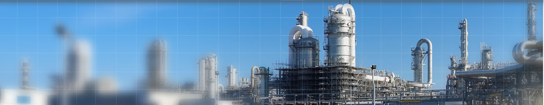
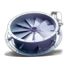
In general, control dampers will be of the opposed louver type, and isolation dampers can be either parallel louver or guillotine. Double parallel louver dampers and double guillotine dampers also get consideration. If a damper must open or close quickly, the louver type is the only practical choice. A few butterfly dampers have gone into circular ducts adjacent to flue gas desulfurization systems, but this type of damper is not common in power plant applications.
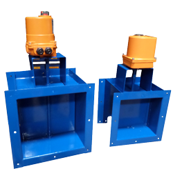
Fan Dampers
At the inlet to centrifugal fans, either a parallel blade louver damper or a radial vane damper is sometimes the choice. These damper types impart whirl to inlet air when damper vanes are partly closed, reducing power need. Fully open, however, the damper causes a slight loss in the system.
Service conditions vary widely through the unit. Clean low temperature air at the forced draft fan inlet contrasts with ash laden, wet, corrosive gas before or after the scrubber. Temperature changes of nearly 300°F can occur suddenly when an air heater fails.
Gas Turbine Exhaust
In gas turbine combined cycle or heat recovery systems, a damper directs hot exhaust to the stack or to the recovery boiler. Although the gas is clean, it can be corrosive, and it's always hot, around 900°F or higher. Specialized damper types are required. Fast opening and tight closure are important.
Baghouse Dampers
For baghouses, both regular dampers and special poppet types are in service. The poppet varieties meet the need for a quick acting short stroke and tight sealing inside the
Isolation And Leakage Performance
A damper's isolating capability is the most frequently discussed means of evaluating damper performance. However, is widely abused and there is no industry standard for its application. Also, once a damper is installed, rarely if ever is leakage actually measured.
Most Engineers must design flue gas systems based on some type of leakage rate across dampers. High leakage could effect the overall efficiency of the whole system. An example would be scrubber bypass damper where leakage escapes directly up the stack and effects EPQA emission compliance. With maintenance applications "Zero Leakage" is required, and is defines as having no flue gas leakage past the closed damper. This is accomplished by using purge air to create a positive pressure barrier . In recent years guillotine dampers have been used in place of double louver dampers. Guillotines require less maintenance, have smaller seal air fans, and do not have a large pressure drop across the damper when open.
A damper's isolation capability can be stated in several ways.
Leakage
This is the most common way to show performance. The various leakage paths are added up to get a total area. The theoretical leakage rate is then calculated. Leakage is stated as either volume (CFM) or mass (Lb./Hr). In both cases the actual density of the flue gas is a factor. Flue gas density changes with temperature, and at higher temperatures the gas has a lower density causing higher leakage rates. Pressure also is directly related to the amount of leakage. At higher pressure there is more force to push the gas through the leak paths causing higher leakage.
When comparing leakage rates or requesting tighter sealing dampers it is common to state the percent of leakage compared to the total gas flow rate when fully open. However, as shown on the attached example, the percent of leakage can vary greatly due to temperature and pressure although construction has not changed.
Area Blockage
This is an older method of comparing isolating capabilities of dampers, where the percentage of total are blocked off when the damper is fully close is stated. Although good for evaluating damper construction the area blockage method does not directly relate to leakage rates, since leakage will change with pressures and temperatures, while this leakage area may not.
This method is used by some people to give the impression that the damper is tighter sealing than an actual leakage rate would indicate.
When dealing with damper sealing performance the following is recommended
Seal Air System/leakage Criteria
The seal air system is sized to develop a pressure in excess of the normal system differential pressure. To accomplish this a fan flow requirement must be accurately determined.
Fan flow is determined using the general Bernoulli Equation and applying it to leakage based on mass flow through an orifice. The amount of gas able to pass from one side of the damper to the other is called the leakage, Q. When expressed in terms of standard cubic feet of air per minute the symbol is QSCFM. The calculation of the leakage is based on the mass flow through an orifice.